Nene Valley Railway has a few stationary railway items on display near its Wansford station. One of them is a small ground frame with three levers which uses tappet locking, the most common type of mechanics used in the UK for locking in interlocking frames. The following pictures show a few details of this frame. Unfortunately, in my incomplete understanding at this time, I did not take photos of all the important parts, so the locking diagram for this very small frame is not completely explained here.
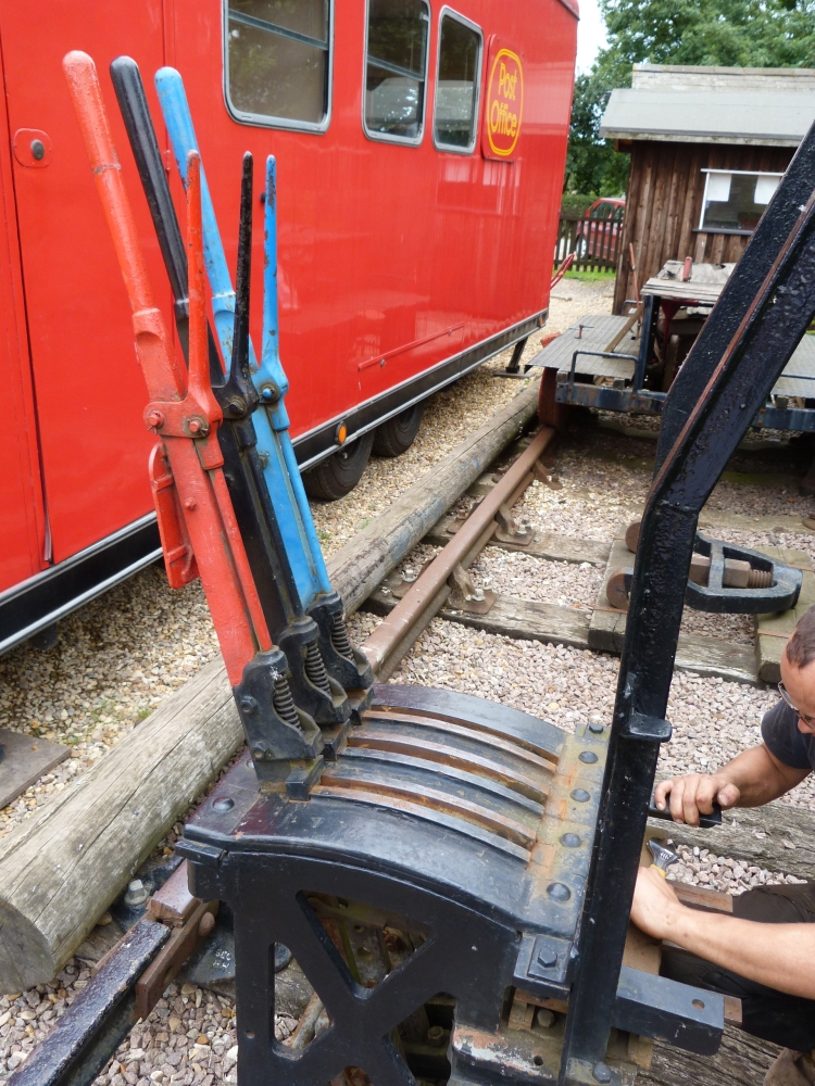
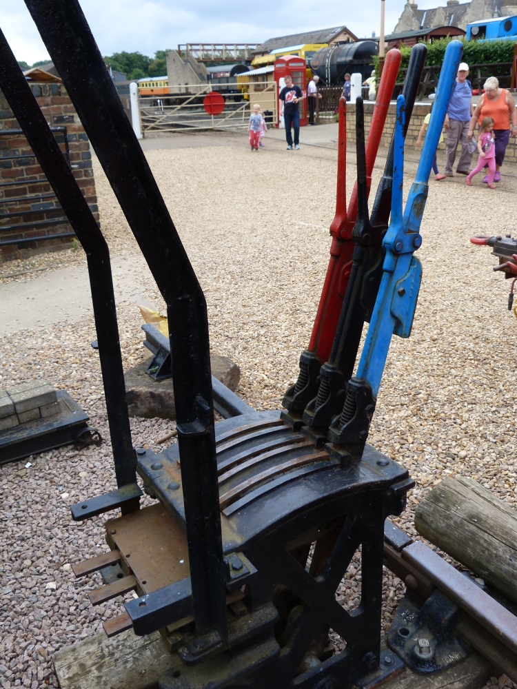
By the way, if you are interested in mechanical interlockings, this book might be for you: Railway Signal Engineering (Mechanical), by Leonard P. Lewis, published in 1912.Here is the frame with all its levers in normal position. The levers, from left to right, are
- a blue lock lever (usually, I assume that this would be the lever that unlocks the ground frame; so it would need some sort of unlocking device, either an "Annett's lock" or some electrical lock—but I did not see the one or the other on this frame);
- a black points lever; and
- a red signal lever.
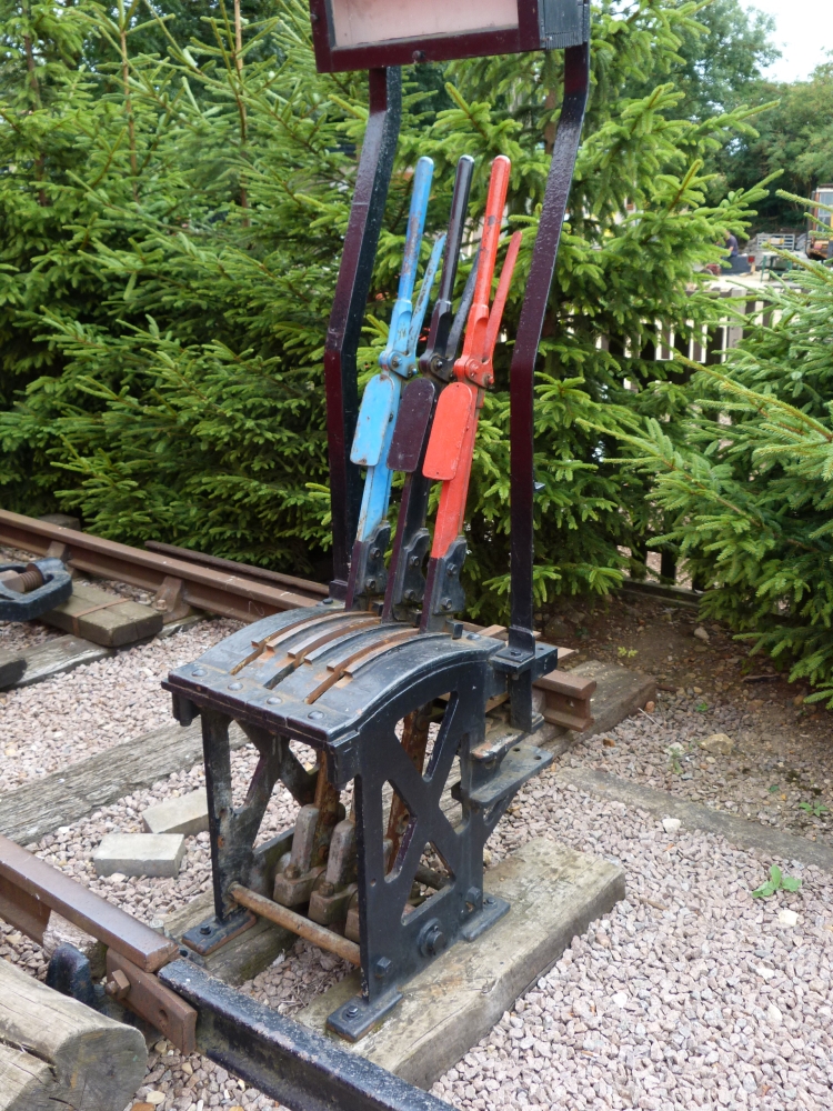
Ground frame, Wansford (NVR), 22.8.2013
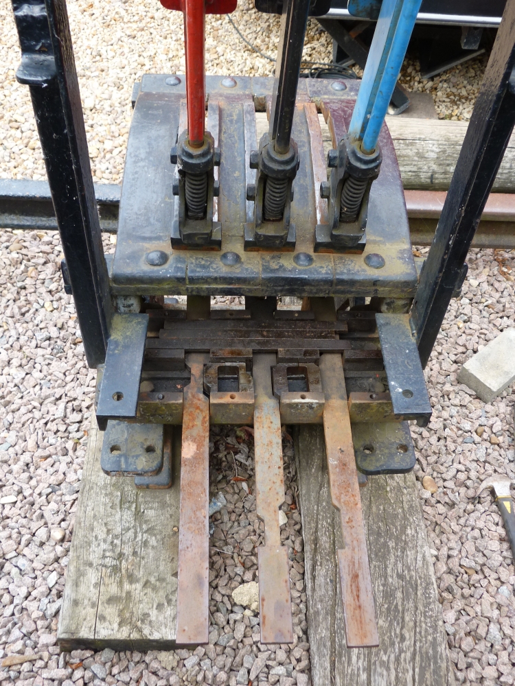
At the back of the frame, three long bars or "tappets" can be seen protruding from a covered box:
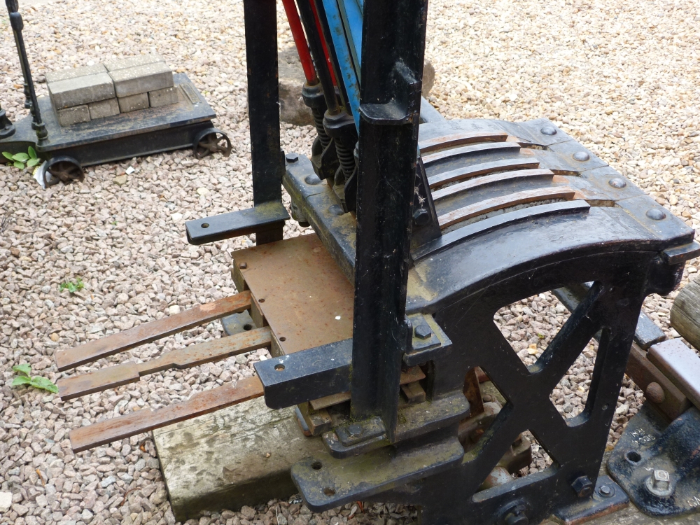
Ground frame with all levers normal, Wansford (NVR), 22.8.2013
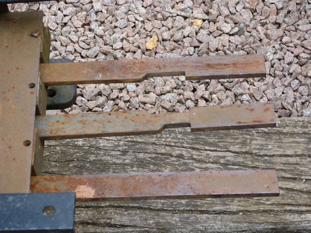
Tappets of ground frame, Wansford (NVR), 22.8.2013
The tappets are directly connected to the levers (in some more sophisticated designs, the tappets are moved by the catch handles for additional safety—I will not explain this here):
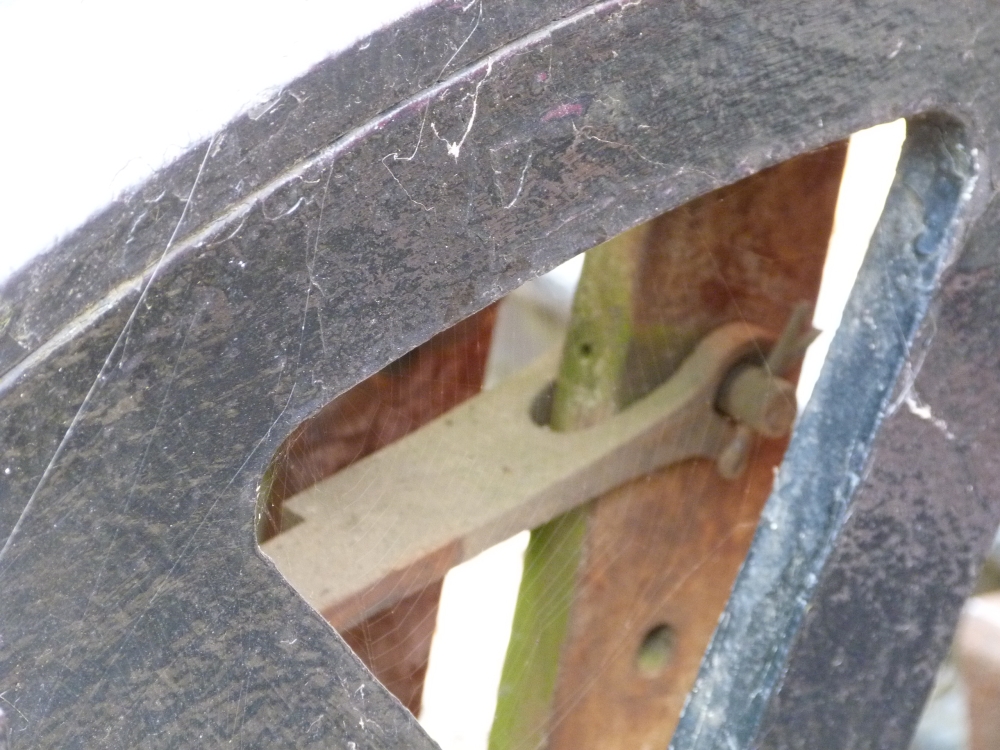
Attachment of tappet to lever, Wansford (NVR), 22.8.2013
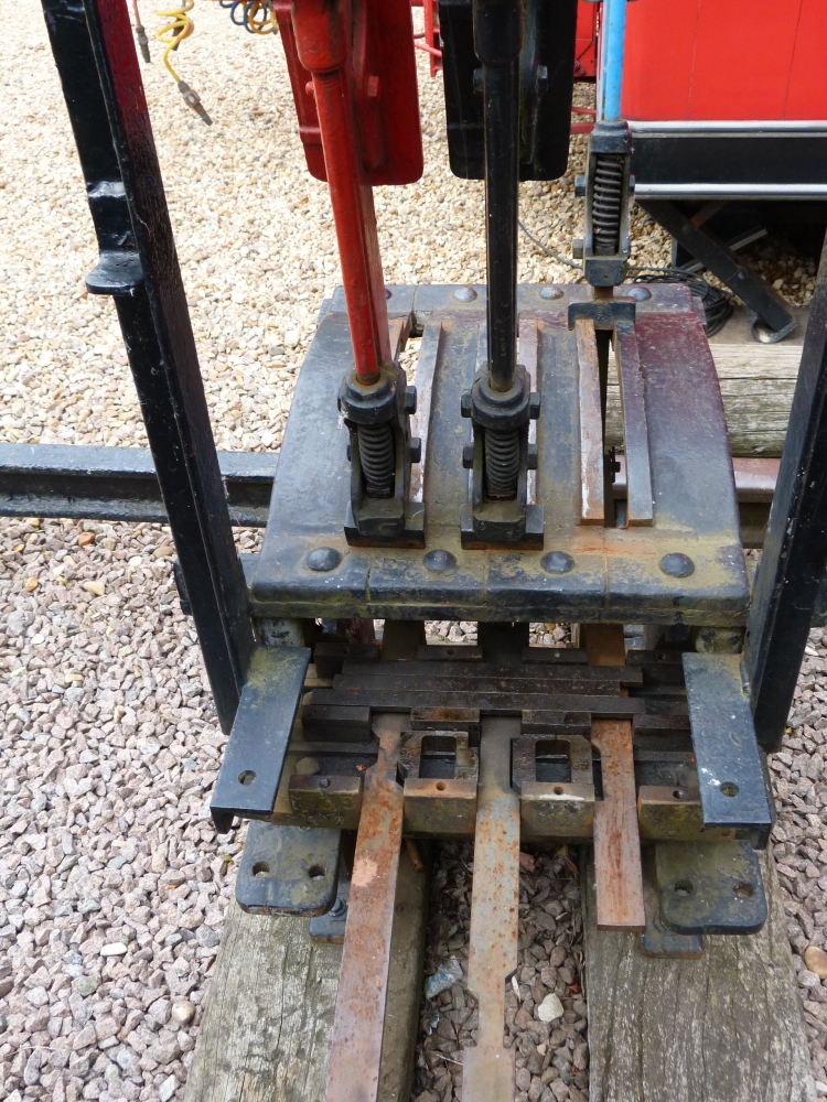
Joel of the NVR was kind enough to open the locking bed so that one can see some of the details inside:
Ground frame with all levers reversed, Wansford (NVR), 22.8.2013
Here is what we see:
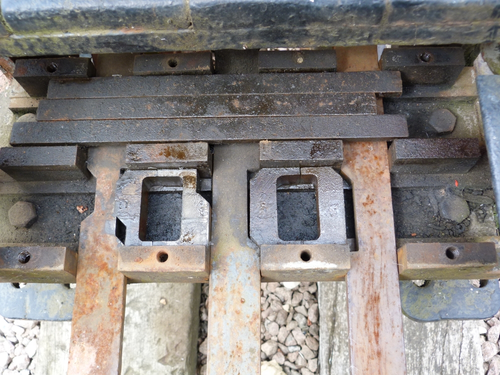
Ground frame with open locking bed, Wansford (NVR), 22.8.2013
One can see that segments are cut out of the tappets, and funnily shaped pieces are inserted between them:
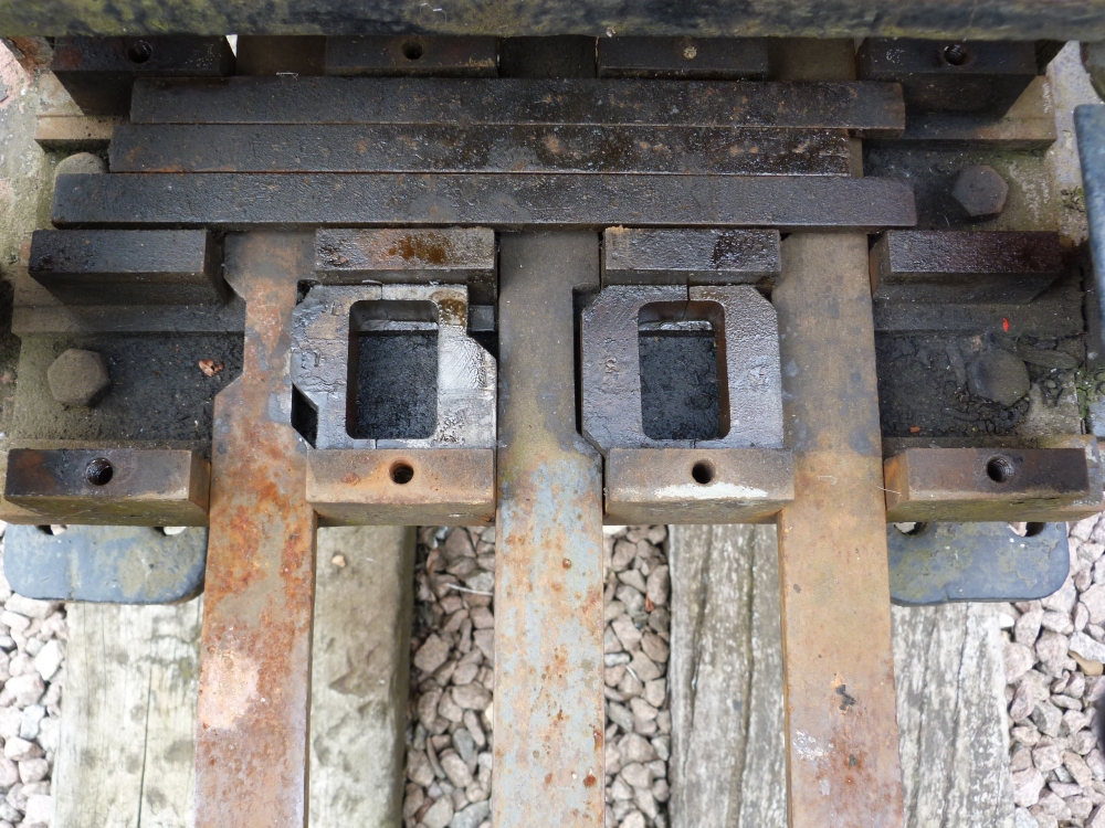
Locking bed of ground frame, Wansford (NVR), 22.8.2013
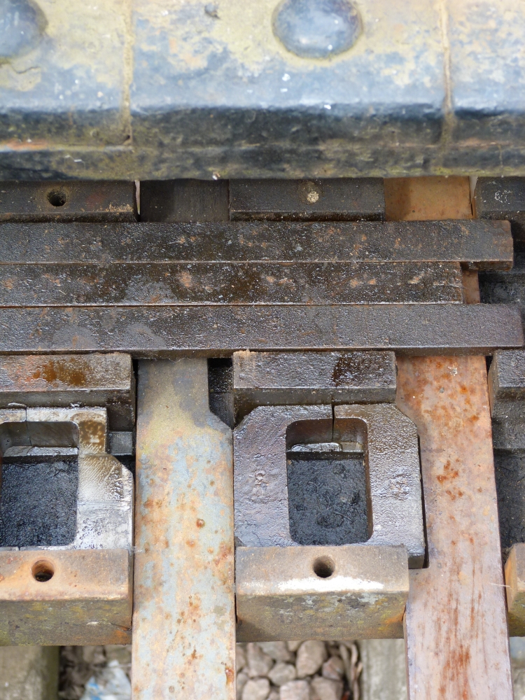
The cuts as well as the pieces in between (the "wedges") are tapered at their ends: Therefore, moving a tappet will force the wedge out of the cut—however, this is only possible if there is a corresponding cut in the adjacent tappet! In the following picture, the blue lock lever has been pulled to its reverse position, and its tapped has therefore moved so that its cut is now exactly opposite the right wedge:
Ground frame with open locking bed, Wansford (NVR), 22.8.2013
Locking bed of ground frame, Wansford (NVR), 22.8.2013
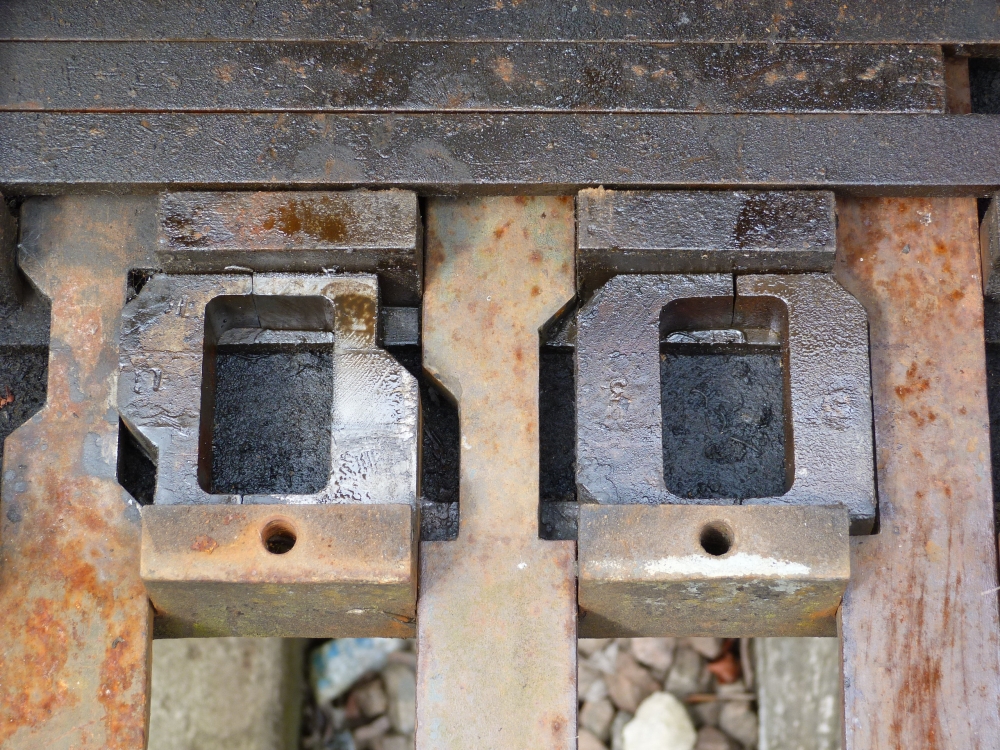
When the black points lever is now pulled, the taper at the cut will shift the wedge to the right into the cut in the lock lever's tappet. The following picture shows the situation when the points lever has only been pulled a little bit—the cut in its tappet is still partly visible, but the wedge has already been pushed to the right:
Locking bed of ground frame, Wansford (NVR), 22.8.2013
Whereas the points lever can be moved freely in this situation, the lock lever cannot be moved if the points are reversed, as its tappet is locked into place by the shifted wedge.
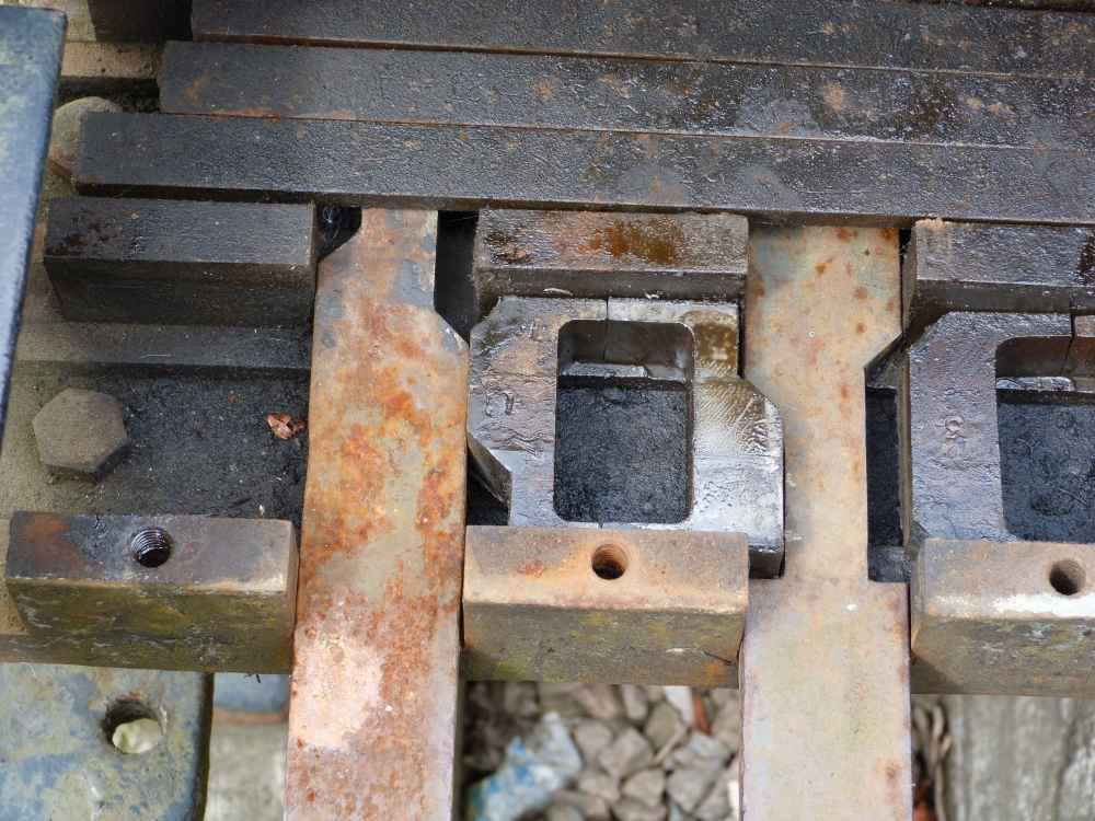
An identical dependency locks the signal lever against the points lever. The cuts and the corresponding wedges are formed differently here, although that would only be strictly necessary in a larger frame with multiple "channels" for the wedges. Moreover, the cutout of the signal lever's tappet on the left does not really match the wedge—these parts seem assembled somewhat ad-hoc from pieces used elsewhere before:
Locking bed of ground frame, Wansford (NVR), 22.8.2013
Now we start pulling the signal lever:

Ground frame, Wansford (NVR), 22.8.2013
This will pull the corresponding tappet, which therefore forces—with the taper of its cut—the left wedge to the right so that it now moves into the cut in the points lever's tappet, which is therefore locked in position:
Locking bed of ground frame, Wansford (NVR), 22.8.2013
Finally, we end up with all three levers reversed:
Ground frame with all levers reversed, Wansford (NVR), 22.8.2013
My pictures of this frame end here ... unfortunately, I did not take additional pictures of a connecting bar, which is crucial in this case to lock the blue lock lever when the signal is reversed. A picture of such bars will follow later when I show parts of another frame. There, I hope to explain a little more about more complex frames.
No comments:
Post a Comment