12SA frames were mainly used on secondary lines, for example on the Murtalbahn, the Ybbstalbahn, but also around Ried im Innkreis. However, older installation were installed on main lines, like my 12SA, which stood in Steyrling on the Pyhrnbahn, south of Linz. For such cases, they were equipped with additional features not ordinarily used on secondary lines. One such feature, which I described in a previous posting, is the use of levers that survived running through points. In addition to that, my lever frame has the following two features:
- Fouling bars ensured that no vehicle was going over points to be reversed. Due to frequent failures (especially in winter) and expensive maintenance, all such bars had been removed decades ago. However, the corresponding levers had survived on my frame because of ...
- ... the second feature: Routes over facing points were electrically locked so that the points could not be reversed too quickly after a train had passed the home signals. The green boxes on the left and right of my frame contain mechanical devices for this purpose. And because these devices locked the fouling bar levers, which in turn locked the route bars (see this posting with the locking chart), the levers had not been removed—but now only served as an intermediate locking device on the frame.
Let us take a look at these electric locks.
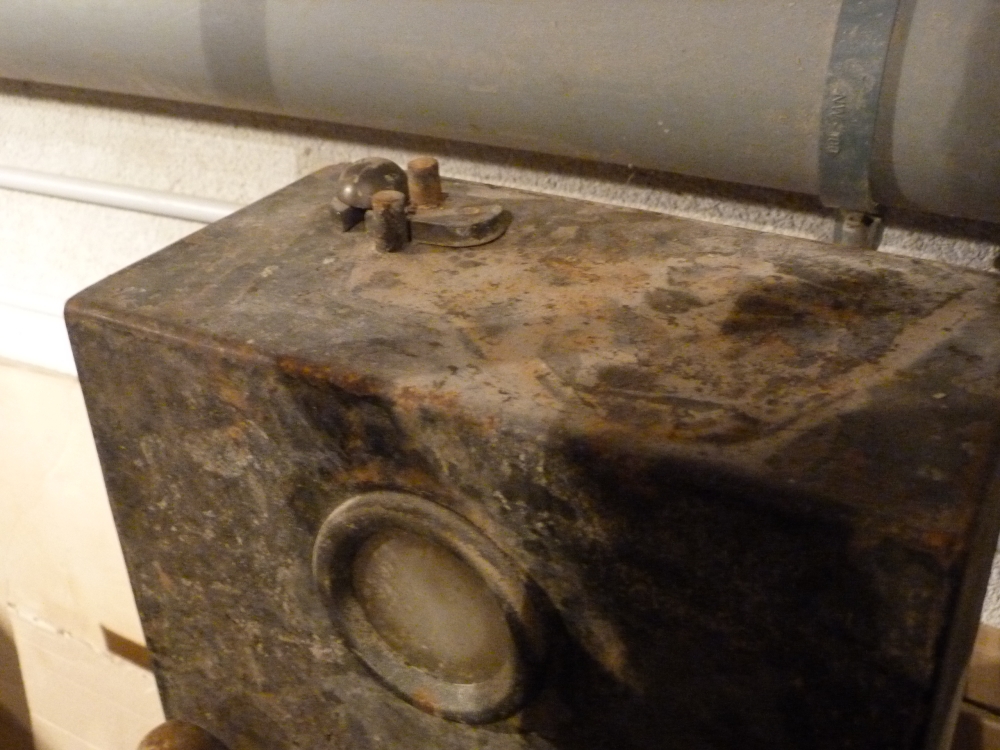
Here is the left box (still dirty from when it was submerged about ten years ago in the Danube and Kamp floods). Behind the glass pane, one can see a white sector which indicates that the fouling point lever is in normal position, and hence the route is not locked:
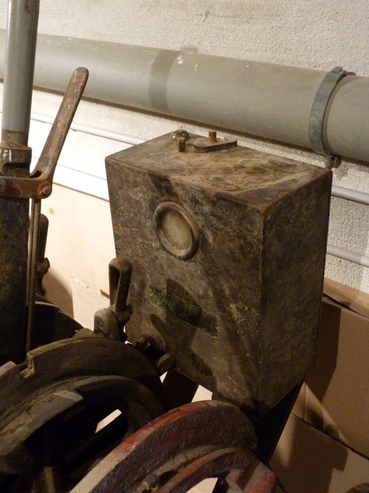
Electric lock in released position
The following picture shows the green sector behind the pane indicating a reversed fouling bar lever, which in turn locks the route bar in reversed position (however, unfortunately, I had removed the connection between the fouling bar lever and the electric lock before taking this picture, which is therefore somewhat misleading. When I find time, I'll replace this picture with a correct and focused one ...):
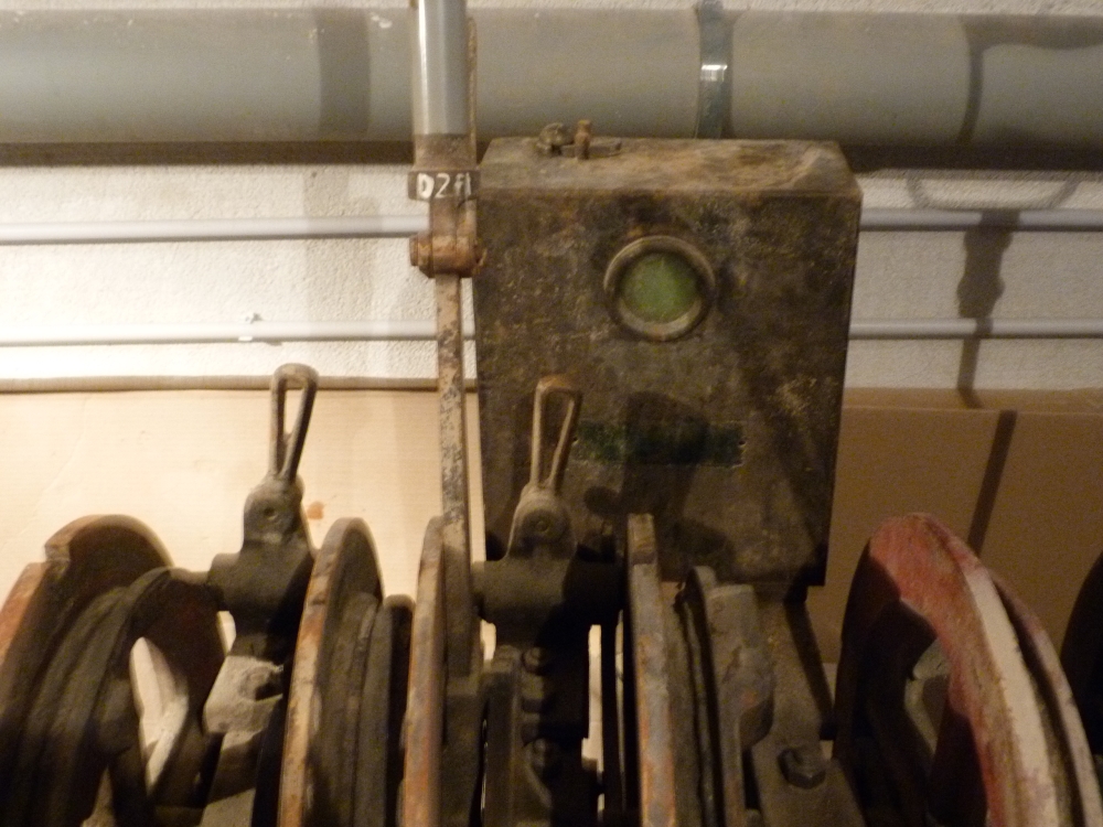
Electric lock in locking position
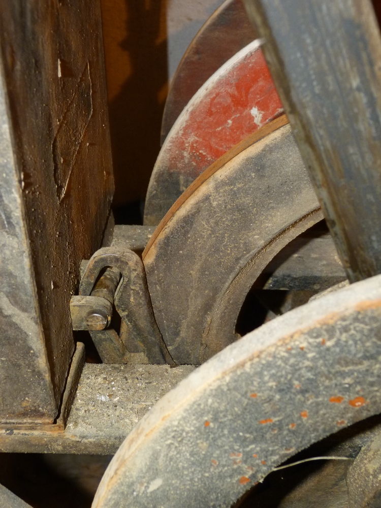
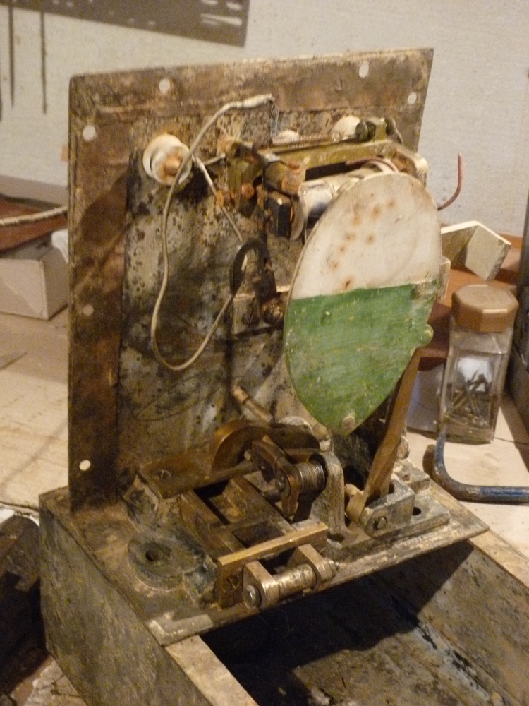
But now, let us look how the electric lock works. This picture shows the fouling bar lever in the middle. One can see that the locking weight lever is extended and ends with an upward part::

Locking weight of fouling bar lever
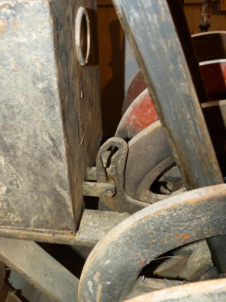
Here is the upward part again, which is crossed by a bolt on a bar vanishing in the electric lock:
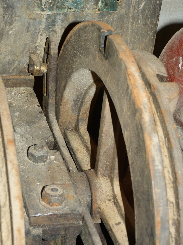
Locking weight lever of fouling bar lever
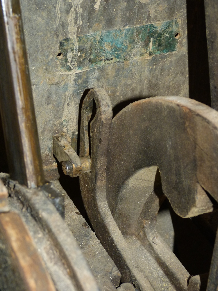
Again the upward part, and one can see that two bars go into the electric lock. Both the fouling bar lever and its locking weight lever are in normal position here:
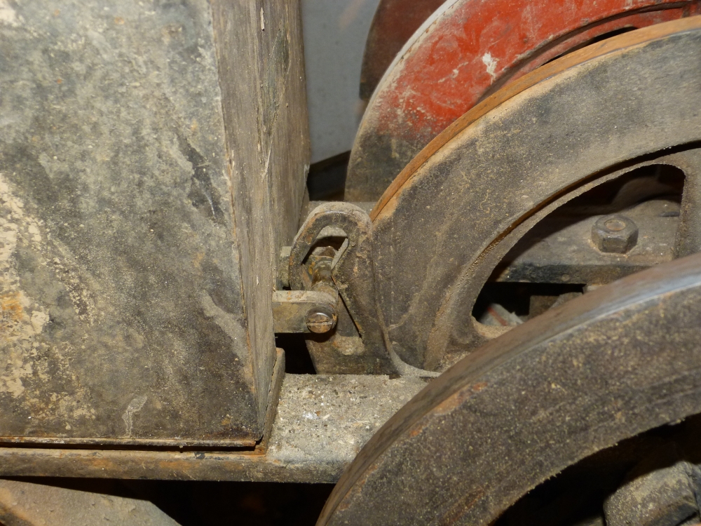
Locking weight lever of fouling bar lever
Now, I lift the locking weight lever (of the fouling bar lever), which is only possible if the route bar for an entry route has been reversed. Lifting the locking weight lever pushes the bolt a little bit towards the electric lock:
Locking weight lever is lifted
I can now reverse the fouling bar lever (actually, my left hand should be on the locking weight—but I needed it to trigger my camera):
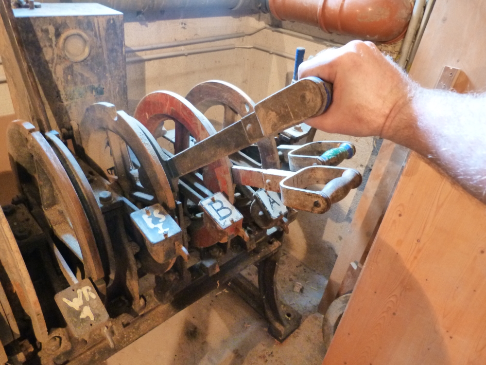
Reversing the fouling bar lever
Finally, the locking weight can be dropped. The diagonal slot pulls the bolt out of the electric lock, which is now locked in this position (we'll see in a moment how this is accomplished):
Locking weight lever dropped (bolt pulled forward)
Locking weight lever dropped (bolt pulled forward)
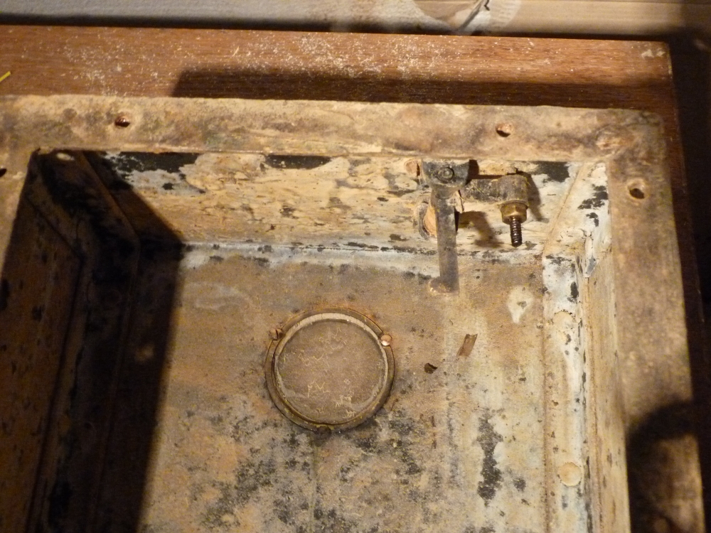
Because of the locked bolt, it is now impossible to lift the locking weight, as this would push the bolt into the electric lock. But what prevents the bolt's movement? To see this, I removed and opened the electric lock. This picture shows the bolt at the lower left:
Opened electric lock
Two videos show the lock's workings. The first one shows the interaction of three levers in the lower part of the electric lock:
- The first one, which I move by hand, will push ...
- ... the second, which in turn will lift the locking disc.
- The third lever, in the back, causes the actual lock by falling behind a link between the two long bars which carry the bolt we saw above.
Internal levers of electric lock
The following video shows the actions inside the electric lock during locking and unlocking:
- Locking starts—as explained above—by pulling the bolt out of the lock. The first and second inside levers lift the locking disc. A bolt at the acute green end of the disc gets hooked into a U hook which holds the disc in its raised position. At the same time, the third inside lever falls behind the link bar, so that the bars to the bolt are now locked in their forward position.
- Either the train (via a treadle) or the station master (via a button on the platform) can activate a solenoid behind the locking disc. The solenoid picks up an armature (which I simulate with my finger) and releases the disc. It falls down and, via the second internal lever, lifts the third lever, which opens the way back for the link bar and hence the bars with the bolt. The locking weight lever therefore can be lifted to release the fouling bar lever, whose reversal in turn releases the route bar.
Locking and releasing
On the top of the electric lock, there is an additional, sealed key. Like the solenoid, this key moves the armature and hence allows a route to be unlocked in case of a malfunction or when a train is cancelled after the route has been locked:
Auxiliary key
Auxiliary key lever
Finally, here is a link to a picture of a similar lever frame preserved at Windischgarsten (the neighbor station of Steyrling):
http://www.wandern.com/land/at/oberoesterreich/urlaubsregion-pyhrn-priel/ausflugsziele/kultur/eisenbahnmuseum.html
Also the museums at Ljubljana (Slovenia) and Hradec Králové (Czechia) have 12SA frames—however, none of the photos I have seen at at stellwerke.pechstein.net seems to show an electric lock like mine and the one from Windischgarsten.
No comments:
Post a Comment