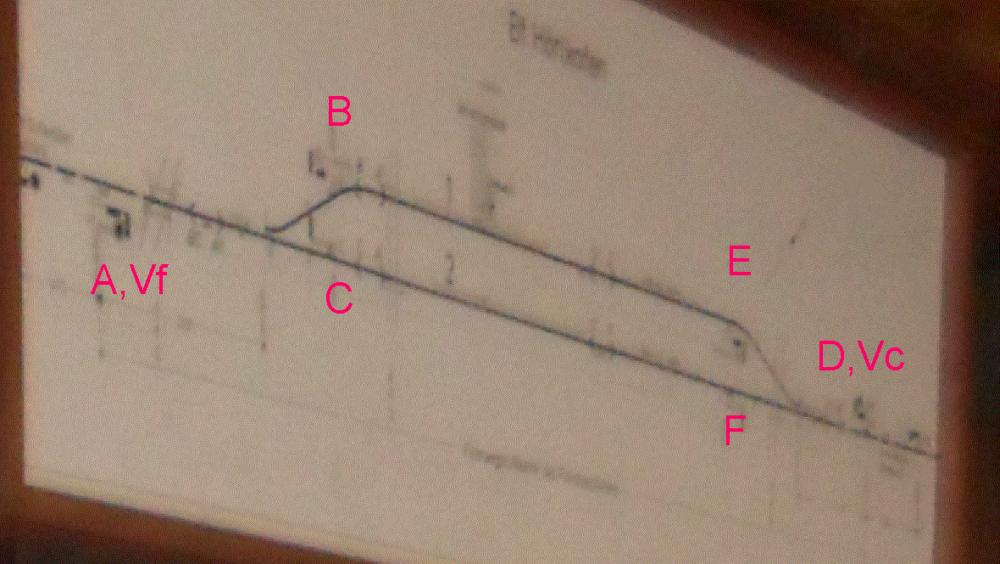
One of the oldest lever frames in Germany is still worked day-to-day on the line from Munich to Mühldorf. Allegedly, it was built in 1899 or 1898—it has been in use in three different centuries! The single interlocking is a mixture of a few types, the main lever frame has been built by Krauss after a design by Bruchsal. In our days, the track layout is as simple as it gets: One main track, one passing loop. The following, enlarged part from an image shown later shows the layout, including the letters of the stop signals and the distant signals located at the home signals:
The interlocking machinery is located in two rooms:
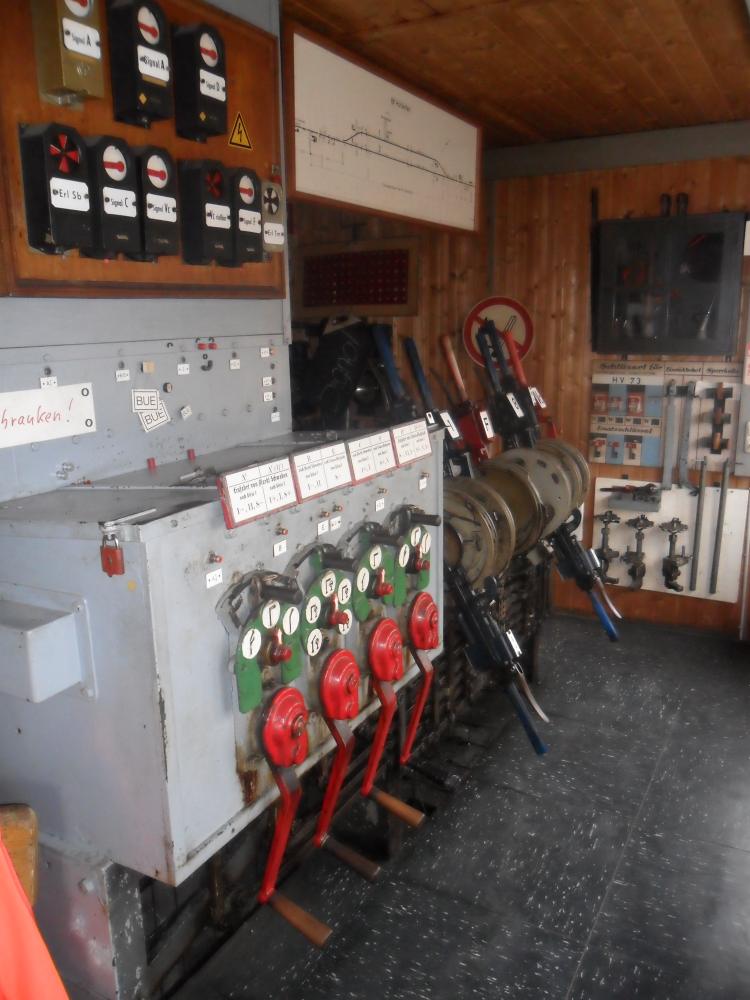
- One contains the lever frame for signals and points.
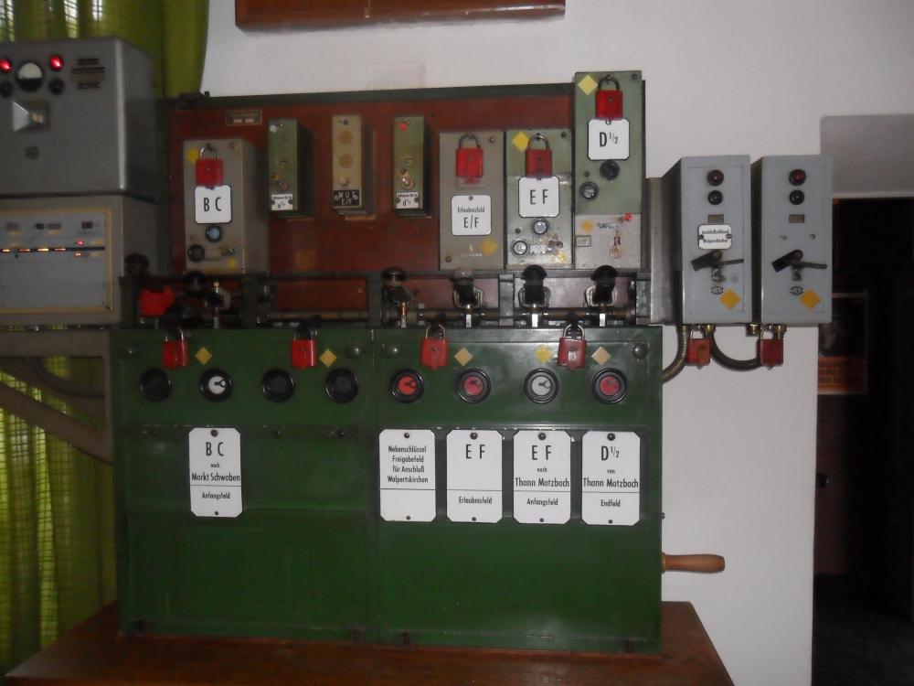
- The other one contains the Siemens block instruments.
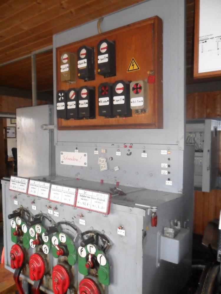
Here is the lever frame ...
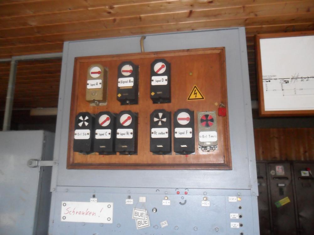
... and here we see the block instruments:
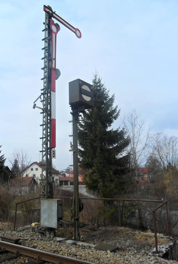
A long time ago, Hörlkofen was equipped with special semaphores used only in Bavaria, which had a special position where the single arm dropped vertically downwards. This indicated that shunting moves were allowed (see e.g. the German discussion at Frage zu Bayerische Signale, Begriff "Ru"). Because of this, separate shunting signals ("Sperrsignal") were not necessary. These Bavarian signals required levers for three positions:
- "stop" (signal 7),
- "rest" (i.e., shunting allowed because no other traffic was allowed; signal 7a according to Röll's Enzyklopädie des Eisenbahnwesens, Bd.9, S.59, Fig.96, 2nd edition, 1921),
- and "clear" (signal 8a).
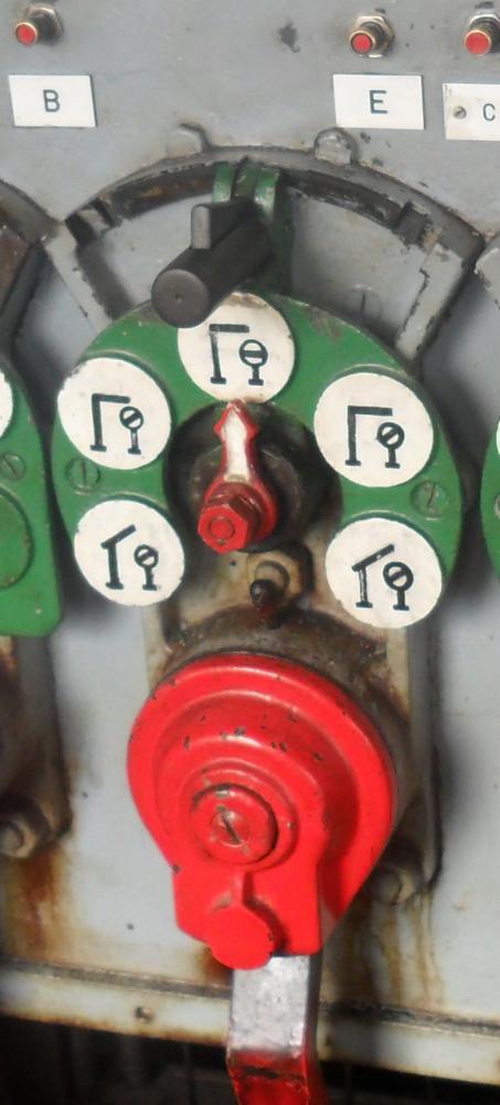
Because of this arrangement, there is only a single mechanism at each signal pair which moves both signals. Here is an image of this setup at starting signal B, with shunting signal Hs 1a:
The Kraus interlockings, like almost all German lever frames, have separate route levers. That lever can be seen above the corresponding signal crank. The route lever has a small catch handle, which the signalman releases with his thumb before moving the route lever to the left or right. This moves the corresponding route bar, which in turn locks the point levers and, where necessary (entry routes), the separate FPL levers.
Obviously, the crank shown above could be used to clear either signal B or signal E.
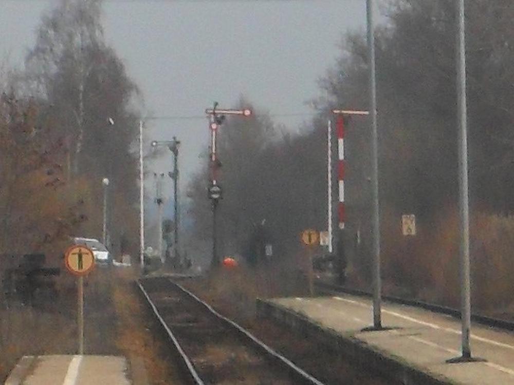
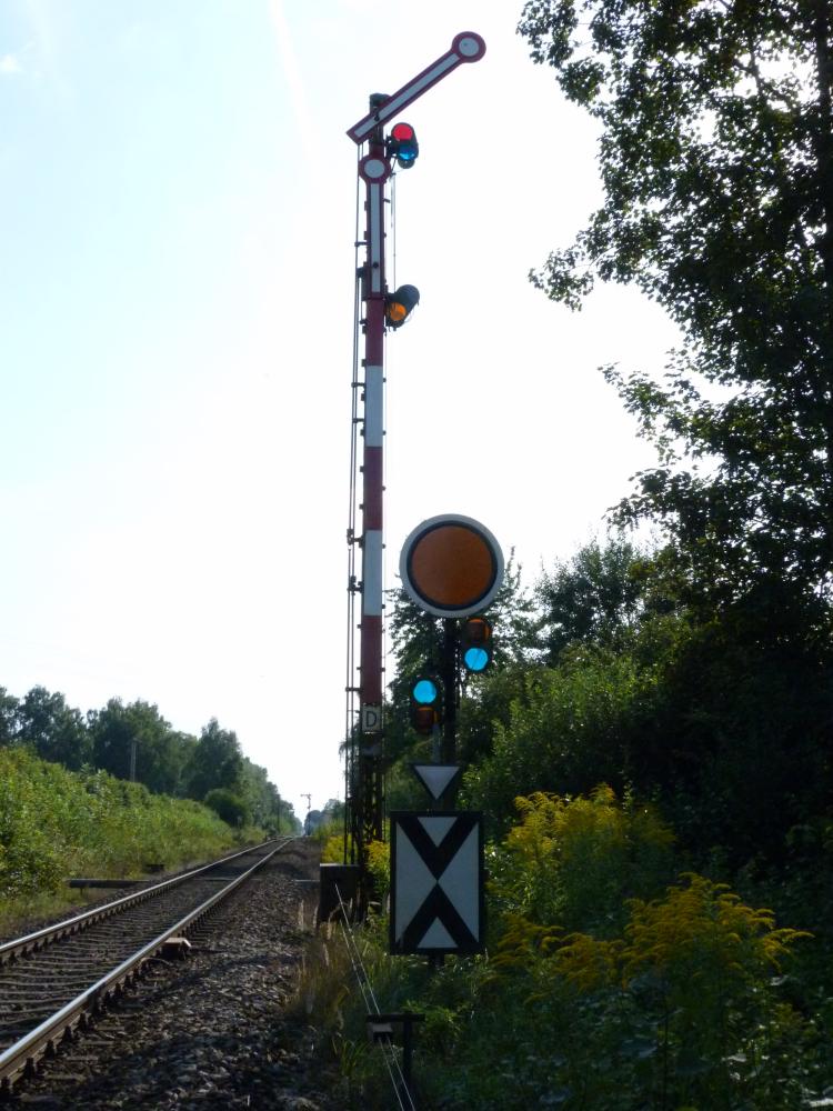
The simple layout of Hörlkofen's tracks is symmetric—the following enlarged image shows the east end of the station, with home signal D, distant signal Vc for the starting signals, and starting signals E and F (I was too lazy to walk the distance to the signals):
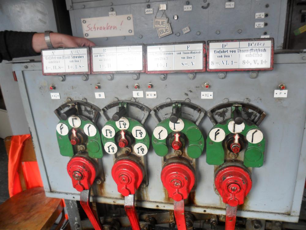
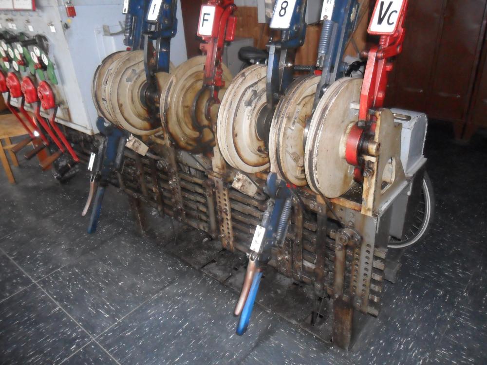
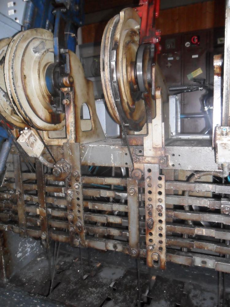
In contrast to the track layout, the lever frame is not symmetric, as you can see on this picture of the cranks:

The outermost cranks are for the two-arm home signals A and D. The second crank controls starting signals B and E on the loop track no.1 and their shunting signals. The third crank, however, controls only starting signal C on the main track! How is the arm of signal F moved? This is done by an actual lever—here is the right half of the frame:
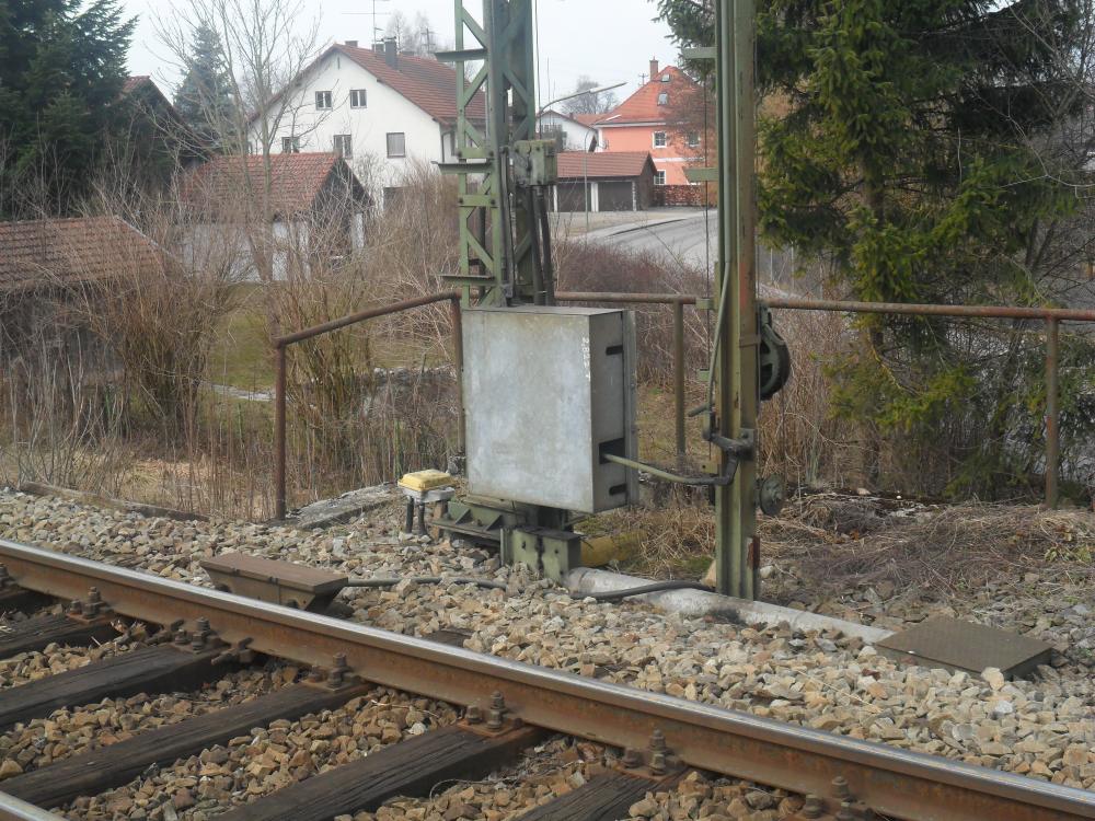
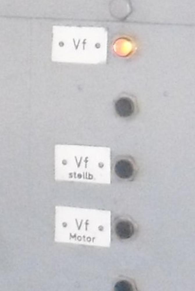
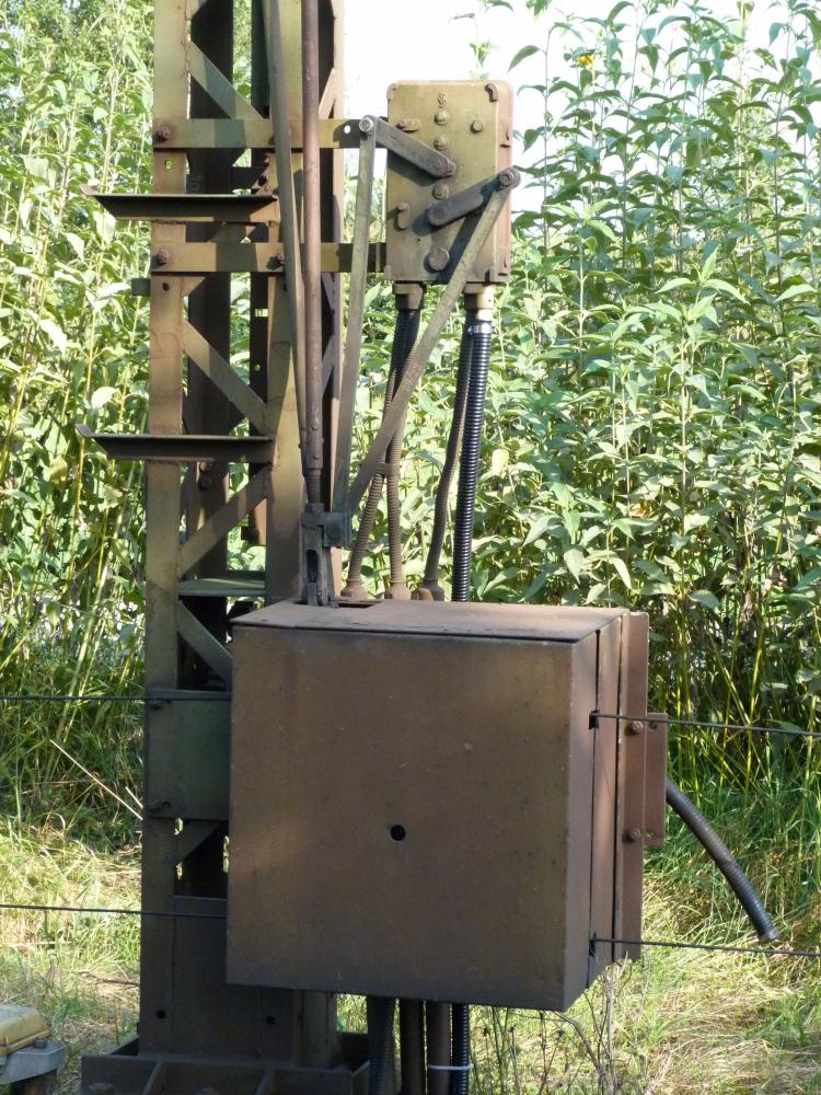
The left red lever is for signal F. The right red lever moves distant signal Vc, which is located immediately in front of home signal D. But where is a lever for distant signal Vf? There isn't any: This signal has an electric drive—both F and A must be clear, then Vf clears automatically. The motor drive is the grey box in the following picture:
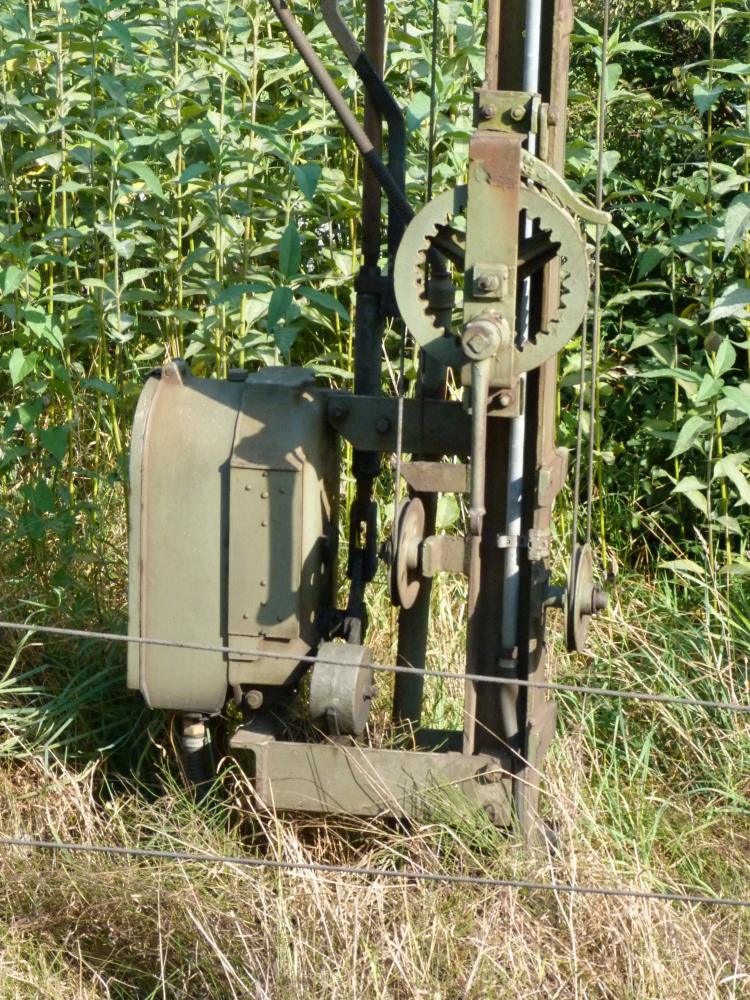
The wheel with cogs on the inside and a few other parts were used in earlier times to lift or lower the gas-lit signal lamps—nowadays, they have been replaced with LEDs, as can be seen later.
Back to the lever frame: Above the signal cranks, one can see small keys. They release lever locks that are controlled by the block instruments. Above the cover at the cranks, one can see signal repeaters showing the actual position of the signals. This is necessary (or at least useful), as German signal arms on lines with block instruments are equipped with electro-magnetic couplings so that the arms fall to the stop position after a train has passed—in the picture of the signals above, you can see the coupling about half a meter above the signal drive mechanism. The following picture shows the repeaters for a route over the main track, where home signal D, starting signal C and its distant signal Vc are all clear:
After the train is in the station, ...
... D and Vc have returned to stop, only C is still clear:
The route lever for starting signal C is still in the reverse position so that points no.1 cannot be reversed:
Near the signal repeater, there are three more "butterfly indicators":
- an indicator showing whether Vc can be cleared;
- two direction indicators which repeat information from the block instruments (Sb = Markt Schwaben side, Tm = Thann-Matzbach side).
By the way, there are no separate levers for the distant signals of the home signals: Each such distant signal is moved by the corresponding signal crank together with its home signal. For this, the signals have a special differential mechanism—on the left, the wires from the lever frame enter the mechanism; on the right, the wires go to the distant signal (Va, in this case):
The lever frame has two levers for the points, which are numbered 1 and 8—most probably, there were lots of additional points in earlier times for various loading tracks. In addition, the two points also require FPL levers both for normal and reverse position. In Germany, the FPL levers are numbered with roman numerals which are independent of the points numbers: In Hörlkofen, levers I and II control the FPL for points no.1, levers V and VI control the FPL for points no.8.
In recent times, both sets of points have been equipped with track-circuits—the blue buttons near the levers are used to release the corresponding lever locks (this is done only to save energy: The lever lock would be uselessly engaged all the time when the points are not occupied without these additional release buttons).
Below the levers, one can see the most prominent feature of this type of lever frame: The open locking bed. The vertical bars are moved by the points and FPL levers. The horizontal route bars are moved by the route levers. Here is the central part of the locking bed:
The hexagonal nuts are used to fasten the locking pieces, which mimic the locking plan. Interestingly, this installation already has three types of nuts:
- The leftmost locking bar (points no.1) use simple nuts;
- The right bar (signal F) uses castle nuts with cotters;
- Both also use modern self-locking nuts.
--------------------
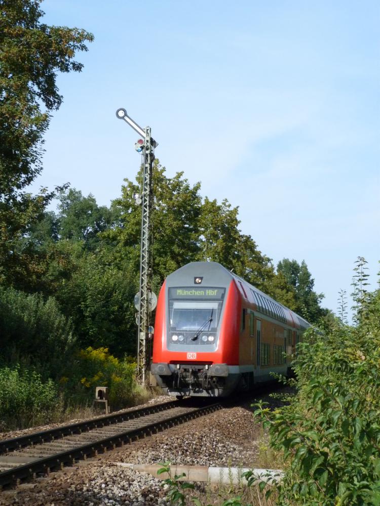
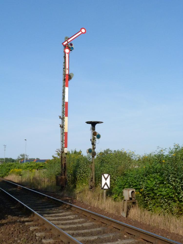
For people who like pictures from the outside, here are a few photos of the signals. First, here you can see signals D and Vc (Mühldorf side), unfortunately with some back light:
Here is the train for which signal D was cleared:
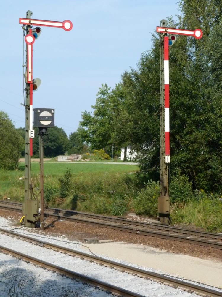
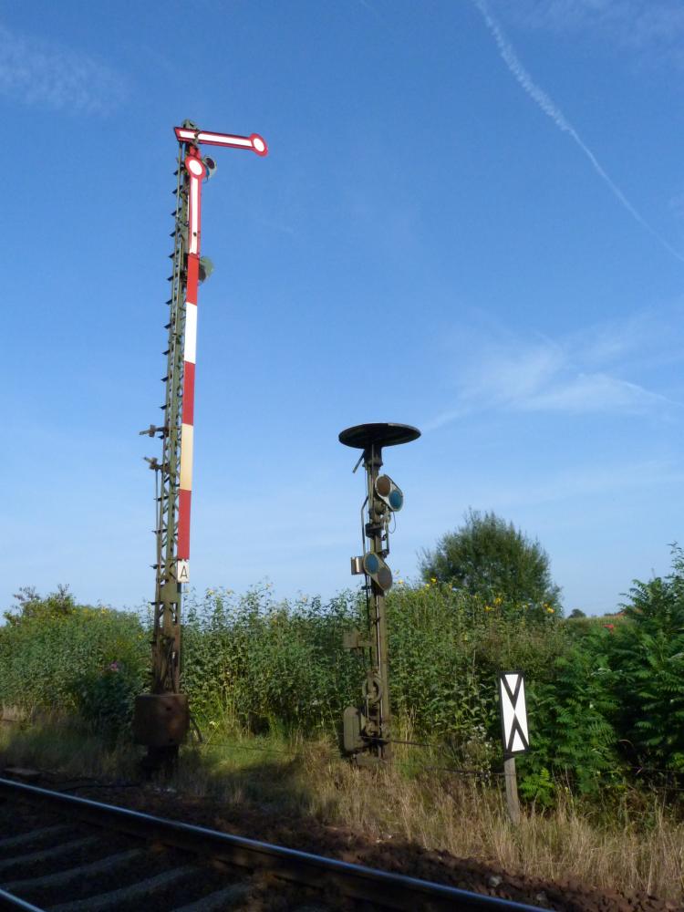
The starting signals E and F on the Thann-Matzbach side; at signal E, one can see the combined mechanism for both stop signal and shunting signal:
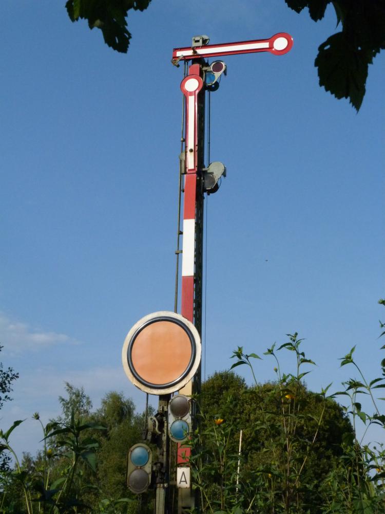
At last, signals A and Vf on the Markt Schwaben side:
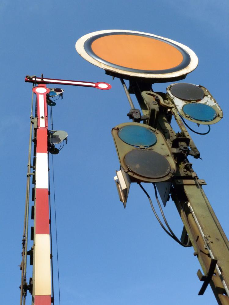
The previous picture also shows the wires leading to the LED matrices that replaced the gas-lit lamps.
The following picture was taken in the moment when the signalman (actually, the train director; see my dictionary for this term) turned the crank to return signal A to its normal stop position; Vf still shows clear, but will drop to danger in a moment:
Again A and Vf, this time framed by green leaves:
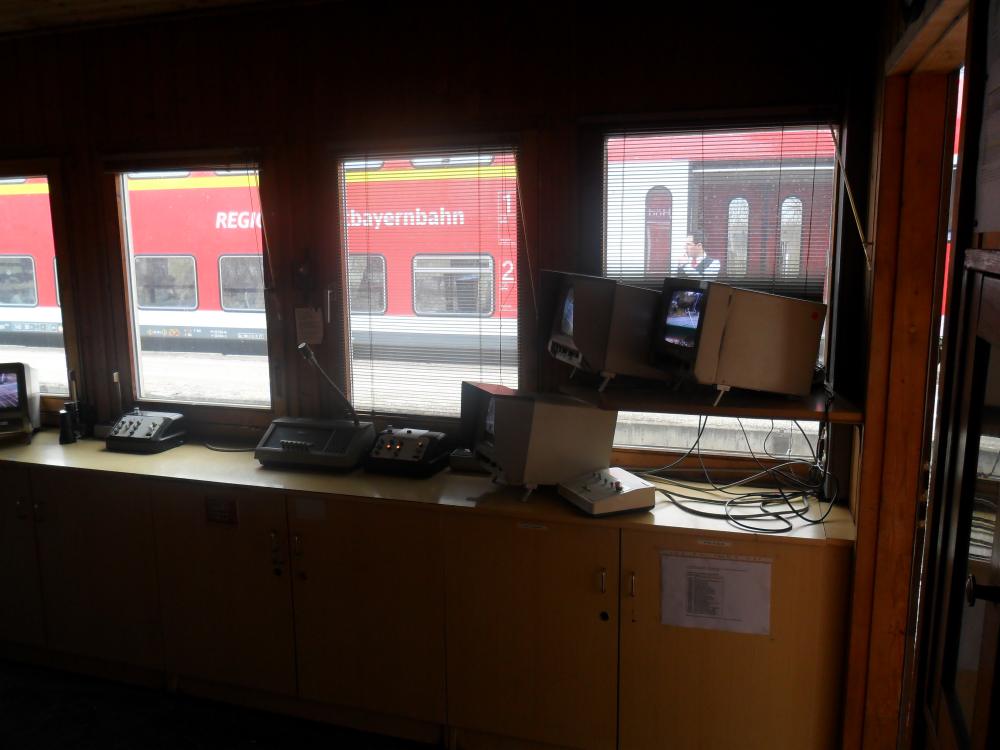
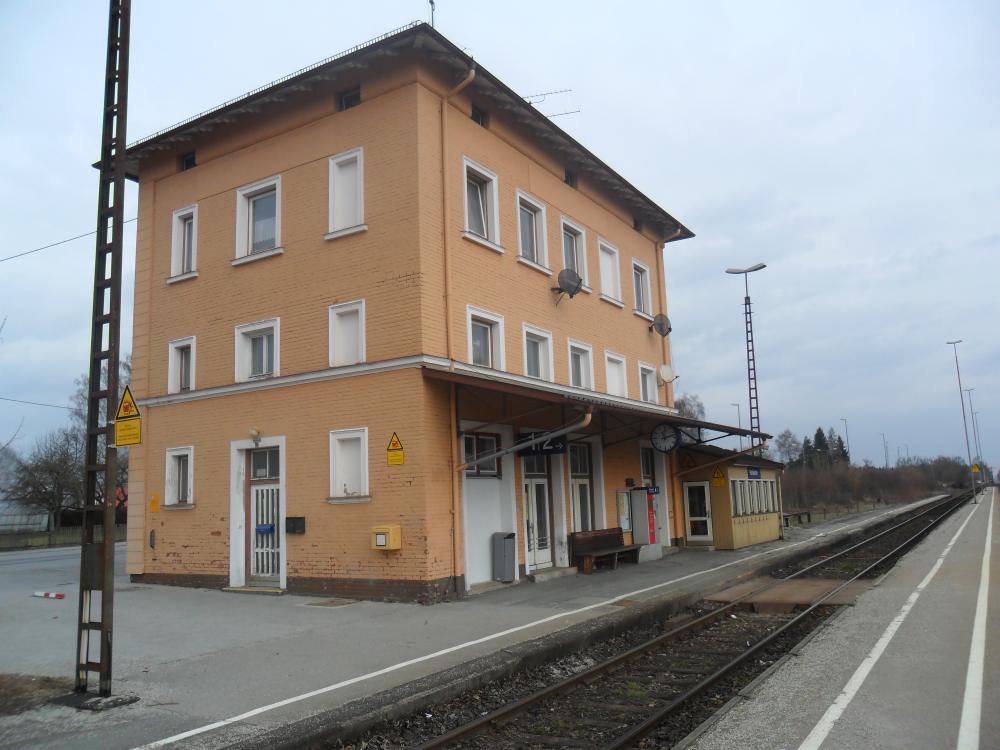
At last, here is a picture of the Hörlkofen station building. The lever frame and the video screens and control panels for the barriers are in the annex on the right side. The traffic bureau is located in the station building:
No comments:
Post a Comment